How to select power MOSFETs for battery-powered BLDC motor drives
Nexperia supplies a wide range of MOSFETs in space-saving package options. This Design Note examines the key product specifications that affect a MOSFET’s performance in a low-voltage BLDC motor drive.

Brushless dc (BLDC) motor technology is gaining adoption at a rapid pace. The power tool segment is a prime example of a market that has seen a shift from the use of small petrol engines, for chainsaws and garden equipment for instance, to efficient mains- or battery-powered BLDC motors. The convenience of portable battery-powered systems in particular has led to substantial growth in this market.
The requirements of the motor drive circuit in these battery-powered tools are very similar to those in other segments such as automation, industry 4.0 and consumer products. These applications typically use dc motors with voltage ratings in the range 4 V to 48 V, and board space is limited.
The brushless motor has grown in popularity because of its superior speed, reliability, and power compared to the traditional brushed motor. The main disadvantage of the brushless motor type is the added complexity of an electronic control module: this module requires many power MOSFETs to control a multi-phase winding, as shown Figure 1.
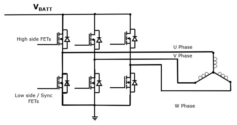
Fig. 1: Typical BLDC motor drive topology
In many of these applications, power dissipation is relatively low. This means that component selection has to consider a wide range of parameters, rather than choosing the device with the lowest on-resistance.
The most important factors affecting MOSFET performance in low-voltage BLDC motors are:
- Drain-source voltage rating
- Product of on-resistance and gate charge, which affects conduction and switching losses
- Power density, which helps to reduce circuit size in space-constrained applications such as handheld drills or cordless vacuum cleaner brush heads
- Dc current rating and pulse-current ratings, so that the MOSFET can handle peak overload and fault currents caused by events such as a locked rotor
- Low drain-source leakage current, which reduces the rate of battery discharge during long periods of inactivity
- Package and board-level reliability, which affect an application’s ability to handle harsh operating conditions, such as extreme temperatures or vibration
Other factors that designers consider when evaluating options for a motor-drive MOSFET include:
- Avalanche rating: high avalanche energy can be dissipated in the MOSFET when exposed to fault currents and long wires
- Safe operating area (SOA): in fault conditions, or when trying to turn off the motor during an overload, the MOSFETs will often be pushed briefly into their linear mode, when resistance rises substantially. A MOSFET with a large SOA can withstand these conditions
- Low gate leakage: to avoid unwanted turn-off events in linear mode
Nexperia has released a range of dual-MOSFET devices housed in an LFPAK56 package which save board space and give improved power density while ensuring that the performance of the MOSFET is not compromised.
For example, the Nexperia PSMN6R8-40HS in an LFPAK56D, clip-bonded package features two MOSFETs, each with a maximum on-resistance of 6.8 mΩ and gate charge of 28.9 nC at a gate-source voltage of 10 V. Each MOSFET has a maximum drain current rating of 40 A, while offering good SOA current capability of 5 A at 24 V for a 1 ms pulse, shown in Figure 2.

Fig. 2: 24 V/1 ms SOA plot for the PSMN6R8-40HS MOSFET
This device is repetitive avalanche-rated, and offers high performance in the other key parameters for BLDC motors. Nexperia has demonstrated the MOSFETs’ reliable performance by subjecting them to high-temperature reverse-bias life testing at 175°C.
Wide range of MOSFET product options
The Nexperia MOSFETs suitable for BLDC motors are supplied in a 100% clip-bonded LFPAK56D package. This package is robust, offering high board-level reliability and providing excellent thermal performance.
A selection of the parts in this portfolio is shown in Table 1.
| Voltage Rating | Part Number | On-resistance at 10 V | Gate Charge at 10 V | Maximum Drain Current | Avalanche Energy | SOA Current, 1ms |
| 40 V | PSMN6R8-40HS | 6.8 mΩ | 28.9 nC | 40 A | 130 mJ at 40 A | 5 A at 24 V |
| 60 V | PSMN9R3-60HS | 9.3 mΩ | 34.2 nC | 40 A | 103 mJ at 40 A | 2.5 A at 40 V |
| 60 V | PSMN011-60HL | 11.5 mΩ | 24.5 nC | 35 A | 118 mJ at 35 A | 2.1 A at 40 V |
| 100 V | PSMN025-100HS | 24.5 mΩ | 38.1 nC | 29.5 A | 83 mJ at 29.5 A | 1.1 A at 50 V |
| 100 V | PSMN038-100HS | 37.6 mΩ | 25.9 nC | 21.4 A | 46 mJ at 21.4A | 1.1 A at 50 V |
Table 1: MOSFETs in an LFPAK56 package suitable for use in demanding BLDC motor applications