How application-specific MOSFETs provide enhanced SOA for hot-swap and soft-start applications
The Nexperia range of application-specific FETs (ASFETs) are MOSFETs that offer special characteristics for certain applications. By optimizing the features of a MOSFET for an individual application, Nexperia has been able to give users substantial improvements in performance and effectiveness.
Hot-swap and soft-start applications benefit greatly from this application-specific approach. For example, telecoms and computing infrastructure runs 24/7, and much of it is based on 12 V or 48 V rack-based systems in which the backplanes are permanently live. To enable the system to be maintained and upgraded while live, its boards and components must support hot-swap operation without needing to power down other parts of the infrastructure.
Design considerations in hot-swap systems
When a board is plugged into a live system, the inrush current must be carefully controlled to protect the components on the board, and to ensure other parts of the system do not experience any power disruption. This is why a hot-swap controller with an ASFET, Q1, is used to limit the inrush current as the load capacitance charges, as shown in Figure 1.
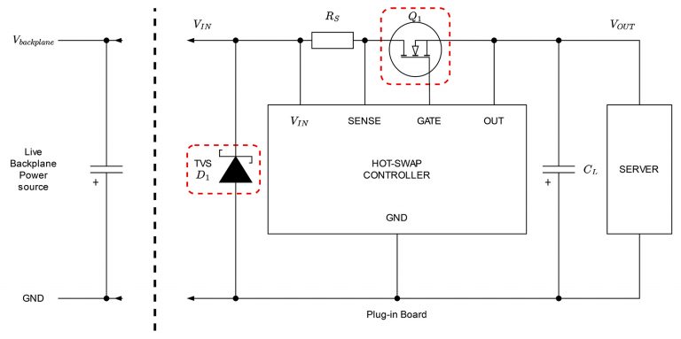 Fig. 1: Typical application circuit for hot-swap controller with ASFET
Immediately after insertion, the gate voltage is controlled by the controller, while the ASFET operates in linear mode: it behaves like a voltage-controlled resistor to limit the inrush current, allowing the load capacitance to charge safely and avoid disturbing the backplane voltage, which is common to other parts of the system.
Once the load capacitance has safely charged, the ASFET is then turned fully on. In this mode of operation, low on-resistance is important, because it minimizes conduction losses and increases system efficiency.
So the main design consideration when selecting an ASFET for inrush current limiting is to combine low on-resistance with an enhanced safe operating area (SOA) for strong linear-mode performance.
Zero temperature coefficient
When an ASFET is turned on, two competing effects determine how its current behaves with increasing temperature. As the temperature rises, the threshold voltage falls, thereby increasing the current.
By contrast, the resistance of the silicon increases with increasing temperature, thereby reducing the current. The resulting effect is shown in the ASFET’s transfer characteristics.
The effect of the resistance increase dominates at high currents, meaning that localized heating leads to lower currents. The threshold-voltage drop dominates at low currents, meaning that localized heating lowers the threshold voltage. This condition effectively increases the current within hot cells, leading to thermal run-away.
Consequently, for a given drain-source voltage, there is a critical current below which there is positive feedback and a subsequent risk of thermal run-away. Above this critical current, there is negative feedback and thermal stability, as shown in Figure 2. This critical current is known as the zero temperature coefficient (ZTC) point.
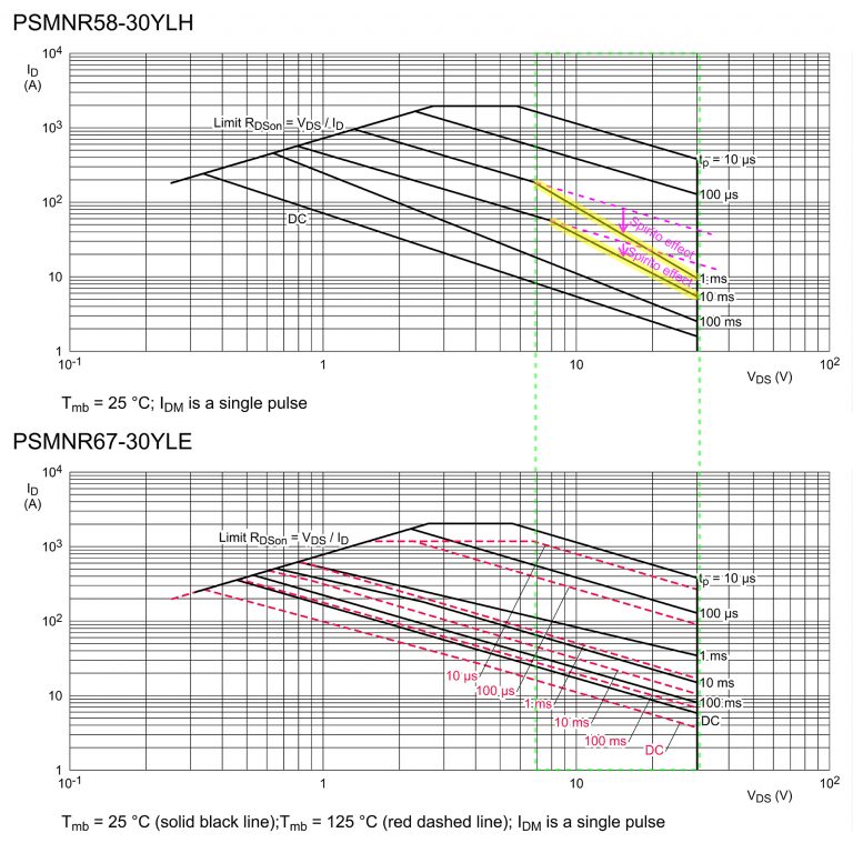 Fig. 2: Positive and negative feedback effects and the ZTC
Below the ZTC point, thermal run-away leads to linear-mode failure. Therefore, for optimum linear-mode performance, the ZTC point should be at a low drain current. ASFETs with a small or negative (dI_D)/(dT_j) provide the best stability.
Figure 3 compares the transfer characteristics of two Nexperia MOSFETs, the PSMNR58-30YLH and PSMNR67-30YLE. As the junction temperature rises from 25°C to 150°C, the increase in drain current in the standard PSMNR58-30YLH MOSFET is 110%: from 40 A to 84 A.
By contrast, in the PSMNR67-30YLE ASFET, this drain current increase is just 28%: from 40 A to 51 A. This means that the ASFET gives greater thermal stability.
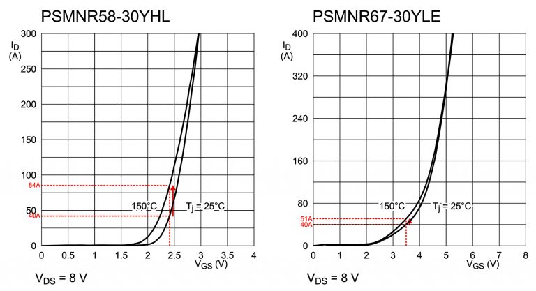 Fig. 3: Comparison of linear-mode performance of the PSMNR58-30YLH standard MOSFET and the PSMNR67-30YLE ASFET
Spirito effect
The Spirito effect describes the electro-thermal instability that arises from uneven die heating and the formation of hot spots. This happens because the gate-source threshold voltage has a negative temperature coefficient at values for drain current that are below the ZTC current.
The consequence is to reduce the ASFET’s ability to dissipate power when the drain-source voltage is close to its upper limit according to the device’s SOA chart, shown Figure 4.
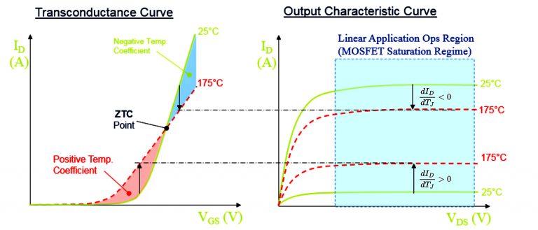 Fig. 4: The Spirito effect demonstrated in a comparison of a standard MOSFET, the PSMNR58-30YLH, with the PSMNR67-30YLH ASFET
SOA graph at high temperature
An SOA graph shows continuous and peak drain currents as a function of drain-source voltage when the mounting base temperature is 25°C and 125°C. Avoiding the need for thermal derating calculations, the graph also shows that performance greatly exceeds the theoretical derating values, as shown in Table 1.
| Temperature | Source | Current Capability |
| 25°C | SOA graph | 40 A |
| 125°C | Derating theory | 12 A |
| 125°C | SOA graph | 31 A |
Table 1: The PSMNR56-25YLE ASFET’s SOA current capability at 12 V for a 10 ms pulse
Broad portfolio of ASFET products
Nexperia ASFETs for hot-swap applications are supplied in a 100% clip-bonded LFPAK package. This package is robust, offers high board-level reliability, provides excellent thermal performance, and is compatible with other manufacturers’ Power-SO8 package footprint, shown in Table 2.
| Breakdown Voltage | Part Number | Maximum On-resistance at 10 V |
Maximum Drain Current | SOA Current Capability at 12 V for 10 ms at 25°C |
| 25 V | PSMNR56-25YLE | 0.63 mΩ | 320 A | 40 A |
| 25 V | PSMNR68-25YLE | 0.77 mΩ | 285 A | 30 A |
| 25 V | PSMNR89-25YLE | 0.98 mΩ | 270 A | 27 A |
| 25V | PSMNR98-25YLE | 1.11mΩ | 255 A | 23 A |
| 25 V | PSMN1R6-25YLE | 1.88 mΩ | 185 A | 16 A |
| 30 V | PSMNR67-30YLE | 0.70 mΩ | 365 A | 40 A |
| 30 V | PSMNR82-30YLE | 0.87 mΩ | 330 A | 30 A |
| 30 V | PSMN1R0-30YLE | 1.11 mΩ | 275 A | 27 A |
| 30 V | PSMN1R1-30YLE | 1.26 mΩ | 265 A | 23 A |
| 30 V | PSMN2R1-30YLE | 2.17 mΩ | 160 A | 16 A |
Table 2: Nexperia ASFETs in the LFPAK56 package
To help designers to quickly find a suitable ASFET, Nexperia has added parameters for SOA performance to its online parametric search tool for ASFETs for hot-swap and soft-start applications. Designers can specify a current capability for a 1 ms, 10 ms or 100 ms pulse period when searching for the most suitable ASFET.