

This article deals with the increasing importance of Functional Safety (FuSa) and the resulting requirements especially in the industrial automation application field, with a focus on motion control applications.
Product solutions in hardware and in software with dedicated features meet these requirements now and in the future. The FuSa developer is supported through pre-certified software, enabling the ability to focus on the application specifics, rather than spending additional work on the necessary basic functionality. Thus, allowing a fast forward design of the circuitry with minimized time and cost spend. Hardware product examples and their FuSa-related features are introduced to enable the developer to take advantage for a more sophisticated design.
The reader of this article does not necessarily need to have expertise or existing knowledge on the topic of FuSa, since selected FuSa related terms are explained.
Introduction
- New high-performance MPU
- Standards and definition of selected terms
- Systematic approach, identification of required SIL, V model, iterative steps, certification
- Application example for motor drive, redundancy, diversity
- Product features supporting different SIL in MCU, sensor and memory
- Support for developers
- Trends in FuSa and outlook
- Summary
Functional Safety (FuSa) and its implementation on various applications is an important, often challenging, design task for the developer. The aspect of avoiding harm to humans, animals and assets, such as technical equipment and the environment, are becoming increasingly eminent. The terms IIoT, Industry 4.0, Artificial Intelligence and others, indicate the speedy changes which are ongoing in the industrial and other application areas. In such applications, including industrial motion control, the requirements regarding FuSa are getting more complex.
In this article an excerpt, out of a wide product range of components, will provide some device examples and their key features to ensure that the required safety level can be reached. These components are both hardware devices and software tools. They support the developer of an application, also called the system integrator, in the design process and ease the cost-effective implementation of FuSa functions. Cost in this context means not only the price of the components, but also the costs for development in material, time and logistics as well as other requirements for creating a market-ready application solution. Especially for the designer with little or no experience, the determination and calculation of these costs can be a challenging task.
New high-performance MPU
The first aspect is that high speed and precise motion control is a requirement in the industrial field, especially for robotics applications. The second aspect is the increasingly sophisticated task of integrating FuSa features at the same time. One example of this is cobots or collaborative robots which directly interact with human workers. The third area is the communication, interfacing with external components, such as via Ethernet.
Combining these requirements is a challenge for developing complex multi-controller, MCU/MPU, systems, requiring substantial resources. These resources include the work force, time spent for design, development, testing, and verification including final certification.
Facing these challenges, Renesas has developed a tailored MPU solution which combines motion control, FuSa and network communication within one device, the RZ/T2M. The RZ/T2M consists of 2 CPU ARM® Cortex® R52 cores assigned to dedicated tasks. One CPU core acts for the high-precision, high-speed motion control (CPU0), and the other CPU core is dedicated to FuSa and network communication tasks (CPU1). For FuSa, this concept offers diverse advantages, illustrated in Figure 1.

Fig. 1: Functional safety system example within a motion control application. Source: Renesas Electronics Corp.
The functional safety system example in a motion control application uses Renesas RZ/T2M, comprising the safety relevant components inside the dashed line. In the redundant concept, a part of CPU1 is dedicated to FuSa. By cross-monitoring with an external Safety CPU a Hardware Fault Tolerance (HFT) of 1 can be achieved.
The high-precision motion/motor control is dedicated to the CPU0. Which can fully provide its calculation capability to this task.
The advantages of this concept related to FuSa are:
- Only one additional external MCU/MPU related to FuSa is required, otherwise two additional MCUs/MPUs would be necessary
- Available software enables isolation, self-diagnostics, and safety network, see below for more details
- Isolated safety-dedicated peripherals
- Hardware and software separation of real-time and network communication tasks resulting in high reliability and a high-performance operation
- Easier realization, as less H/W is required with less space and layout, leads to a reduced bill of material (BOM)
The available software covers three areas on the coexistence of safety related and non-safety relevant software for communication and motion control.
- Self-diagnostics, detecting permanent faults from CPU1 and shared memory (SRAM).
- Functional safety platform, realizing a redundant system, which separates the MCU/MPU control, MCU/MPU tests and user applications into safety and non-safety applications.
- FuSa over EtherCAT (FSoE) application, which is ETG.5100 S® V1.2.0 compliant
The self-diagnostics software is pre-certified by TÜV Rheinland which saves development time and cost on the developer side. Failure simulation injection raises failure detection coverage to about 90% (SIL3*) compared to usual of only about 70 % coverage.
Basic FuSa functions are provided by Renesas. Therefore, concentration is required only on the application-specific FuSa functions which are needed by the designer.
FuSa over EtherCAT is available, and Profisafe is under development.
The example in Figure 1 includes several terms related to FuSa. This article introduces several terms, as well as concepts and products for realizing FuSa in the application.
Standards on FuSa
Driven by experiences of several dangerous accidents in the past, the topic of FuSa was created. The root, or basic standard is IEC 61508 which was introduced in 1998, followed by additional diverse application-specific derivates for aerospace, automotive, railroad, robotics and others, considering their individual safety aspects.

Market researchers such as MarketsandMarkets™ forecasts an increasing worldwide turnover in the functional safety area at a compound annual growth rate (CAGR) of around 9%.
For differentiating functional safety from security, the following explanation can be applied. Functional safety concerns the protection against unintended hazards which are immanent to the device, whereas security deals with intended threats from outside the device which should be minimized, and ideally evaded.
Implementing FuSa-related measures to an application ideally avoids the harm caused by a hazard. But it is often capable only to mitigate the negative impact when considering practically limited resources.
Two types of failures are identified:
- the systematic failure, which is caused by an improperly designed system, where failure prevention needs to be implemented
- the random failure, which is caused by a hazard, where fault control needs to be implemented

Fig. 2: Triangle of mutual dependencies
One of the most important terms in FuSa is the Safety Integrity Level (SIL). It defines the level of safety to be achieved in a specific application and environment. In the industrial application area four levels are defined: SIL1 is the lowest, up to SIL4 which is the highest. There are other application-specific levels defined, such as ASIL in the automotive area. ASIL are based on the same considerations, but they are not 100% equivalent to each other.
Important influence factors on the determination of the required SIL are the risk factors:
- Which level of harm can the hazardous event cause, severity
- How probable, how often and how long the hazardous event can occur, exposure
- Possibility of avoiding a failure of the system at a hazardous event, controllability
A method to analyze and detect failures, reduce failure in time (FIT) rates and support meeting targeted SIL is Failure Mode Effects and Diagnostic Analysis (FMEDA). This is based on the failure rates of the individual components applied in a system or subsystem.
Here it is essential to seriously consider the requirements by the hazard analysis and risk assessment, in order neither to over- nor under-rate these requirements. In most cases a residual risk remains, since it is not possible to achieve zero risk by deploying a finite effort to avoid a malfunction.
FuSa development process and architectures
The overall FuSa-related development process follows the so called V model, shown in Figure 3. Starting from the risk analysis, going step by step down from system requirements level, to the detailed system design, to the implementation development. Then upwards by testing and verifying the different integration levels with the goal of the final certification. Each of these steps need to be checked and achieved, by iterating the individual step, before the next step can be approached. The implementation process is applied to both hardware and software developments.
This process can also be described as sequence of Concept, Design, Implementation, Testing, Certification and go live.

Fig. 3: Simplified V model implementation
Functional safety architectures offer the possibility to increase the achievable SIL. When using devices which would not reach the requested or necessary SIL, when deployed alone.
The nomenclature applied is the number of channels which need to support a valid output signal out of the available number of channels. Creating a redundant system architecture is often an appropriate method to increase the SIL in case a single device or channel itself would not be capable of reaching the required SIL. So called decomposition into parallel devices is only capable of achieving a lower SIL.
As example of SIL 3 achieved by applying redundant systems which are each capable of reaching SIL 2, is shown in Figure 4.

Fig. 4: SIL 3 achieved by applying redundant systems
It is not always necessary to deploy two physically separate devices for achieving the higher SIL. For example, in the area of MCU/MPU, a dual-core device with lock-step operation can also be a solution. Typically, such lock-step operation can be implemented, for example, by a two-core MCU/MPU where each core works on the same task but at a different point in time or cycle. After cycle alignment, the calculation results of each core are compared. In case a different result occurs, a failure is detected, and a counter measure can be triggered.
The following table shows typical examples of architectures indicating the parameters of availability of a system and its reliability. The simplest system is the one-out-of-one, or 1oo1. A simple redundant system is 1oo2 where at least one channel needs to deliver a valid signal out of two in parallel available channels. The D indicates an additional diagnosis function. These and further architectures are shown below.

Table 1: Architecture examples
The Reliability column is relative to the other architectures, and shows how likely it is for this architecture to deliver correct results. The Availability column indicates the relative readiness for operation, and the Effort column indicates the investment required relative to each of the different architectures. This effort is related to the design complexity, for example, the number of necessary devices in a circuit topology as well as meeting the volume and weight requirements. In addition there are the assembly and sourcing costs and the necessary time spend required. This time spend comprises the designing process, testing, assembly, logistics for sourcing and storing the devices, and more. The SIL column shows the achievable level relative to each architecture. Clearly the optimum compromise needs to be found for reaching the necessary safety goals by not overshooting the cost, timeline, or time to market, and other constraints.
The Hardware Fault Tolerance (HFT) describes in a FuSa system how many faults it can cover without losing its intended safety function. For example, a redundant architecture 1oo2 has HFT = 1, since one fault occurring does not stop the system from working.
Implementation of FuSa, an application case
A simplified example for implementing FuSa into a robot application is applying a dual core MCU/MPU.
The goal is to achieve a safe stop of a robot arm movement by switching off the motor in case of a hazardous event. Especially when this robot is used as cobot, or collaborative robot. Therefore, it is even more important to avoid injury to humans and not to damage or destroy assets.
The left side of Figure 5 shows the initial situation where the 3-phase motor is supplied by three power lines (pl). The power line contacts can be opened for switching off the motor and closed for running the motor. The pl contacts are switched by a control unit. Based on several input signals, the control unit decides whether to open or close the pl contacts. In this example, four input signals generated by sensors influence the control unit: The proximity sensor detects if a person is too close to the robot arm; a speed sensor to avoid too high movement speeds; a temperature sensor to avoid over-temperature stress; and a manually triggered emergency stop button signal.

Fig. 5: Example of FuSa in a robot application with dual-core MCU/MPU.
The SIL to be achieved determines how detailed the failure analysis needs to be and finally decides how much effort needs to be taken for the necessary risk mitigation or ideally the failure avoidance.
The risk analysis in this example leads to following possible failures:
- General malfunction of the control unit such as S/W, H/W, memory content, under- or over-voltage
- Failure at the sensors, such as a damaged sensor, short-circuit to supply/ground. Failure by broken wire connection sensor to the control unit
- Failure by broken wire connection from control unit to motor contacts
- Failure by damaged power line contacts, open/closed
A possible safety architecture shows risk mitigation by the following measures:
- Redundant control units with mutual monitoring of correct function
- Redundancy of sensors, doubling the sensor set for reduced failure risk. PWM signal on sensor connections to control unit, a short to ground or supply can be detected by watch-dog
- Redundant connections of the control unit to switch the power line contacts to the motor
- Redundant monitoring of status feedback, Safe Torque Off (STO), from power line contacts to control unit PWM signal on control lines
- In series connection of power line contacts. In case one pl contact fails to open, the series connection of a second pl contact increases the likelihood of a safe opening, switching of the motor.
For quantifying the individual risk of a single device failing, there is data available from the components manufacturers. The so-called safety manual is an essential document provided by the component manufacturer, listing the safety features, the diagnostic mechanisms and how to use them at system level. Finally, it is possible to decide if the diagnostics mechanisms are sufficient to achieve the required safety goals.
For highly complex devices such as MCU/MPU, diagnostic libraries or self-test libraries are available. These provide test routines for various functions such as register checks, CPU self-test, memory CRC test, oscillator frequency and many more. Running such tests drastically reduces the likelihood of the MCU/MPU failing. Often these libraries are pre-certified from an institute or organization independent from the MCU/MPU manufacturer. In such cases, the required certification process of the application containing the MCU/MPU, is significantly easier for the developer.
Product examples with features related to FuSa
As an example, for improving the diagnostic coverage, DC, of permanent failures during the CPU self-test, the manufacturer, Renesas, has introduced for a verification method for the RX MCU family. This verification method is based on fault injection using the real hardware netlist of the MCU. About 200k possible faults are injected in the simulation environment. The coverage of each fault, if detected or not detected, is evaluated while executing the CPU software test. Renesas claims that this improves the DC from a typical 70% without fault injection, to over 90% applying this fault injection method.

Fig. 6: CPU self-test verification. Source: RENESAS Electronics Corporation
Further support offerings are the pre-certified software development tools for MCU/MPU. These tools allow a faster development process and an overall cost reduction until the final product FuSa certification can be reached. The typical development process regarding a functional safety certified product starts with the introduction and concept phases. The detailed design with testing and iterations for improving the functions follows. The overall inspection completes the design phase. Finally, when the certification is complete, the new product is ready to market. On this partly long, and often costly, path there are several development tools available supporting a speedier pace and cost-effective time-to-market approach. Some of these tools, which can be available depending on the individual device, are reference documents, a compiler certified kit, a self-test S/W kit as described above, reference H/W board, and a FuSa over network application S/W kit.
The application of a cobot, or collaborative robot, is an example for various FuSa related requirements. But also, other applications where fast and powerful movements of subjects and objects are taking place include a conveyor, lifter, escalator and puncher. This is because of the interaction between humans and machine in the same space. This requires reliable sensing at a high availability level of the system. In the simplified example shown above, the proximity sensor detects the position of the human operator. There are several proximity sensor technologies existing which are based on optical, sound wave, RF or capacitive technology principles.
Light barriers can be applied in cases where an immediate stop of motion of a moving object in machinery is required. An interruption of the light beam, by for example a human operator, is detected. This signal is deployed to trigger the movement to stop. The so-called time of flight sensors are also based on optical technology, containing of a transmitter LED and a receiver diode, with the advantage of detecting the distance to an object. This allows not only the triggering of a hard switch off, but a variable slowdown of the machine’s movement speed depending on the distance of the object, down to a full stop of the movement in case the defined minimum distance is not maintained. An alternative technology is based on capacitive principle. At a certain area, an E-field is generated. The E-field may be distorted by an approaching human hand, so the E-field distortion signal and its level can be detected.
A variable slowing down of the machine movement depending on the distance of the object or subject can also be initiated. The same functionality can be realized by applying ultrasonic technology-based distance detection devices. For high-precision distance detection, a radar-based system can be applied. Further technologies are available, such as Passive Infra-Red (PIR) and thermal imaging, especially to detect humans or animals. All these technologies offer the optimum application environment with specific advantages and disadvantages. The designer needs to understand these for deciding on the optimum solution for the individual requirements.
The principle of redundant designs can be applied here. By paralleling sensor elements for achieving a higher SIL of the overall sensor. Figure 7 illustrates this in a block diagram deploying two Hall sensor elements for position detection, such as angle sensing of a robot arm. Two ADCs and two MCUs feed signals into a comparator. The sensor output signal is only valid when the two parallel channels show the same signals from the parallel MCUs fed into the comparator.
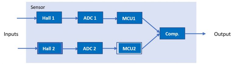
Fig. 7: Applying two Hall sensors for achieving higher reliability through redundancy
Also, for the sensing of other physical values, such as current, voltage, temperature, speed, humidity, particles, gas, visible light image sensing and more, various sensors based on different technological principles are available. Future Electronics can give more details on applicable sensors.
An even higher SIL can be achieved in applying sensors based on different or diverse technologies. These allow redundant layouts with higher reliability compared to multiple devices based on the same sensor technology. Because the reason for a single hazard typically impacts only one of the sensor technologies applied, redundant sensing based on a different technology, is more likely not to be impacted. This can include dirt on the sensors which may impact the optical sensing, while the capacitive sensing keeps working as expected. So diverse technologies enable redundant design.
A further concept is to double, or multiply, components with a special safety-relevant functionality. For example, a MCU generates voltage references, voltage supervisor and watchdog signals. Such safety-relevant signals are generated in parallel with separate devices. Both signals are compared in a failure monitor, or safety co-processor. Different signals can be detected which indicate a definable failure. Dedicated counter measures can be applied, such as fail-safe operation. Since there is only selected functionality which is monitored with relative low cost, the overall cost for the application can be significantly lower compared to doubling the MCU for a redundant concept.
Data storage has a high importance for aspects of FuSa. Especially a safe, fast and reliable data set is essential for avoiding, or at least minimizing, negative impact on the system’s safety in case of a hazardous event. The data set can be captured sensor inputs from data logging, as well as program code such as sub routines containing emergency handling instructions. There are specialized memory devices available offering these characteristics for a very affordable investment of time to design, PCB space and cost.
The Excelon™ devices from Infineon deploy F-RAM, ferroelectric nonvolatile memory technology. The F-RAM technology offers highest endurance at 10e14 read/write cycles, 160 years of data retention and therefor a very high level of reliability. Compared to EEPROM, the low-power modes of F-RAM offer significantly less energy consumption. For the realization of a battery driven back-up supply, this enables the circuit designer to spend much less effort to avoid data loss during a hazardous power-down event of the system. The very fast read/write capability of this memory technology predestines it for immediate data logging in an emergency case. The error correction code (ECC) enables single-bit, double-bit auto error correction and triple-bit error detection.

Fig. 8: Excelon™ RAM architecture. Source: Infineon
Especially for safe data storage with data integrity verification capabilities, there is Semper™ NOR Flash from Infineon. In addition to the NOR Flash memory array itself, the devices contain an ARM® Cortex® M0 core, the FuSa oriented safety includes diverse diagnostic circuitry functions, error correction code (ECC) with single-bit error correction and double-bit error detection, cyclic redundancy check (CRC), memory block protection, assured boot with safe boot recovery, and more features. The Quad SPI allows quick data exchange at minimum pin count. The application programming interface (API) allows an easy handling, and the ecosystem contains hardware and software tools. The range of evaluation boards, based on various MCU platforms, offers a wide variety of integration for an individual design. Along with the hardware, an extensive software development kit (SDK) enables the developer to make an effective realization of the design. The SDK includes application examples, drivers for FuSa and Flash, and a hardware abstraction layer (HAL). This helps to achieve a short time to market. Soon, additional Semper™ NOR flash versions, also integrating security functionality, will expand the product portfolio.

Fig. 9: Semper™ NOR Flash nonvolatile memory. Source: Infineon
The above-mentioned products are only some examples of a much more extensive product offering related to FuSa. Future Electronics can discuss individual FuSa requirements and recommend matching product choices. Furthermore, Future Electronics works closely with a dedicated team of experienced consultancy companies. The advantage for the developer is the availability of in-depth design expertise on FuSa topics. The developer is free to choose either for trainings on FuSa, specific support on individual steps in the development process, up to full design support for a FuSa certification-ready design. The FuSa certification is typically done by an external and independent test institute or company in order to have a neutral unbiased view on the application and the FuSa related implementations in the application.
What comes next, trends in FuSa and outlook
The general trend is for more complex systems with higher safety requirements. Examples are partly or fully autonomous working systems such as floor transportation robotic vehicles in an assembly hall environment.
The additional deployment of a failure monitor IC as safety co-processor, targeted to achieve a higher SIL, is another way to take advantage of redundancy in a system. The potential is to use redundant independent components, and monitoring them with a safety subsystem. This is compared to not only using the MCU internal voltage reference, but comparing them with an external voltage regulator with a failure monitor, safety co-processor. This comparison enables the decision whether the system works in safe, or in unsafe, operation conditions. This leads to a significantly higher confidence, compared to only deploying the MCU’s internal voltage reference. The integration of other more FuSa-related features for monitoring in multiple redundant channels in devices such as a MCU, memory or sensor, point in the same direction. These integrated features allow the application designer an easier realization of the product at a faster development schedule.
Systems with implemented predictive maintenance functionality also help to support FuSa and therefore becoming more important. That is because a constant or periodically monitoring of the system “health” can eliminate the root cause of many failures to occur by giving an early warning. Maintaining, repairing or replacing critical components before a (dangerous) malfunction happens, improves availability and reliability of a system.
At increasingly complex systems, the split into less complex sub-systems, which then can be individually monitored, tested and verified much easier and faster is a further trend in order to face the challenges of largely interacting systems.
Safety and security merging
An important trend in the FuSa arena is looking into aspects of IT security as an integrated part. This is a small revolution, since so far FuSa and security topics were seen to be completely separate from each other. Since the interaction between different parts of application, such as data exchange via IT systems to the outside world, is becoming increasingly extensive, with the size of the data volume and how frequent it needs to be exchanged to cloud services, the system has more interfaces to external devices. The more external devices are connected, the more the system gets vulnerable to attacks from outside, resulting in higher risks. The higher the threat level will be, the more important it becomes to avoid malfunction of the device. Such malfunction can be caused by malicious data corruption or other intended attacks on the system from outside the application. At least to mitigate the risk of the potential harm to humans, animals and assets as much as possible, there is the IEC 62443 security standard for industrial communication networks.
Therefore, the experts of both disciplines, FuSa and IT security, will need to cooperate closely in the concept, design and testing phases for solving these additional development challenges.
Conclusion
The importance of Functional Safety (FuSa) is steeply increasing since the rising complexity of the applications and acceleration of the interaction with their surroundings, such as in IT networks. An example is the cobot application for a collaborative robot with its shared workspace with the human operator and the machine. The influence on human, environmental and asset integrity is becoming proportionally more relevant. In the electronics industry, for instance, the manufacturers of semiconductors are continuously developing and improving solutions to enable application designers to face the challenges of implementing FuSa. This is related to the hardware itself, but also includes software tools for the support.
Future Electronics, acts worldwide as distributor for many major manufacturers of semiconductors, passives and electromechanical components. With combined expertise, Future Electronics and its partners will support you in solving your individual FuSa challenges during your application development.
If you want more information, click here.